ΠΩΣ ΦΤΙΑΧΝΟΥΜΕ ΕΝΑ ΡΑΔΙΟΦΟΝΙΚΟ ΣΤΑΘΜΟ ΣΤΑ FM?

ΠΩΣ ΦΤΙΑΧΝΟΥΜΕ ΕΝΑ ΡΑΔΙΟΦΟΝΙΚΟ ΣΤΑΘΜΟ ΣΤΑ FM?

How to Make FM Transmitter?

This tutorial is for making simplest FM transmitter using only one transistor. VC1 is a small, screw-adjustable, trimmer capacitor and its rating should be around 10-100pF. Set your FM receiver for a clear, blank station.
Then, with a non-conductive tool, adjust the capacitor for the clearest reception, rotate it till the receiver receives a sound from the microphone of transmitter. Use the following formula for determining the frequency.
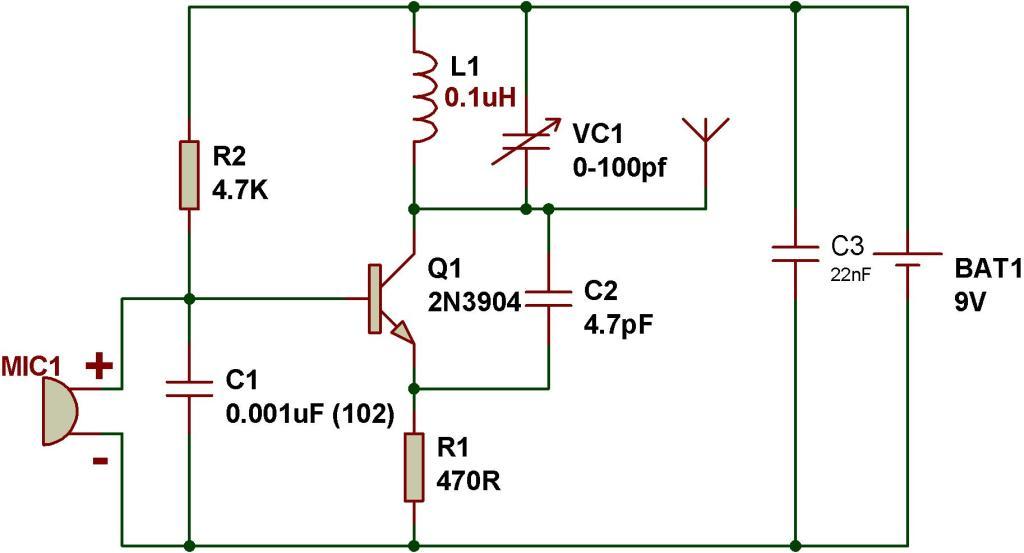
The schematic of FM transmitter:
https://i2.wp.com/electronics-diy.com/schematics/1252/how-to-make-fm-transmitter.jpg
The following shows the components used to make FM transmitter:
1. Transistor, 2N3904:

100W Transmitter Amplifier for 2MHZ

100W Transmitter Amplifier for 2MHZ ΑΚΟΛΟΥΘΗΣΤΕ ΠΙΣΤΑ ΤΟ ΣΧΕΔΙΟ 
100W Transmitter Amplifier for 2200m


100W Transmitter Amplifier for 2200m


This particular transmitter was later shipped up to VY1JA in the Yukon where, thanks to Jay's excellent antenna system, it was heard in Europe as well as in New Zealand during one of the Trans-Pacific Tests! Running 24 volts on the final will produce 100 watts into a 50 ohm load. The transmitter utilizes a 4060 binary counter IC chip as both the crystal oscillator and frequency divider. I used a 2200 kHz crystal along with the 'divide-by' sixteen output to produce a signal at 137.5 kHz. Other combinations of crystal frequencies and 'divide-by' combinations may also be used since the 4060 features divided outputs for f/32 (pin 5) and f/64 (pin 4), among others. You may have a 4MHz crystal or an 8MHz crystal in your junk box that will put you in the band using these output pins.

200-Watt Push-Pull Class-E AM Transmitter for 1500 - 1700 kHz


200-Watt Push-Pull Class-E AM Transmitter for 1710 kHz


Max Carter


  • Input power (DC volts x DC amps): 220 watts
  • Output power (AM rating; into 50-ohm resistive load): about 205 watts
  • Peak envelope power (PEP; at 100% modulation): 820 watts
  • Operating frequency: 1.71 MHz


This transmitter is based, more or less, on equations presented in a 1988 Mark Mallory article detailing a single-ended class-E output stage for a 1-watt transmitter operating in the 160-190 kHz Part-15 LowFER band. The present circuit is a push-pull design and achieves about 93% efficiency at 1710 kHz. The circuit should be adaptable to transmitting in the 160-meter ham band with slight component value changes, or to any frequency within the medium or longwave bands (0-2 MHz) by following the design steps below. The 'as-built' transmitter can be tuned about 100 kHz either side of 1710 kHz (1600-1800 kHz) without modification.
The transmitter has the same basic layout as any AM transmitter, though it may differ in specifics. A block diagram of the as-built unit appears below. Refer back to this diagram as the parts are explained in the article below. Items marked "external" are not described (except in a general way) in the article.

AM Transmitter Block Diagram