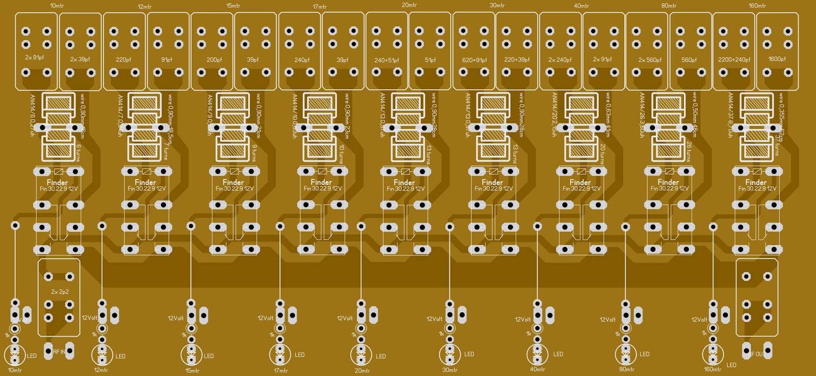
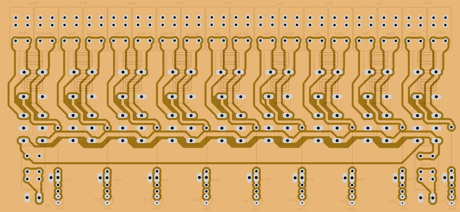
ΚΑΤΑΣΚΕΥΗ ΠΟΜΠΟΥ VHF 220 MHZ 1K WATT ME TO MRFE6VP61K25H
ΠΑΡΑΚΑΤΩ ΤΟ ΣΧΗΜΑΤΙΚΟ ΜΕ ΥΛΙΚΑ ΚΑΙ ΦΩΤΟ ΤΗΣ ΚΑΤΑΣΚΕΥΗΣ

ΚΑΤΑΣΚΕΥΗ ΠΟΜΠΟΥ VHF 220 MHZ 1K WATT ME TO MRFE6VP61K25H
ΠΑΡΑΚΑΤΩ ΤΟ ΣΧΗΜΑΤΙΚΟ ΜΕ ΥΛΙΚΑ ΚΑΙ ΦΩΤΟ ΤΗΣ ΚΑΤΑΣΚΕΥΗΣ
ΠΟΜΠΟΣ ΑΜ HF ME THN GU43Β 1.8 - 30 ΜΗΖ 1.5ΚWATT GU43B
SXEDIA ΚΑΙ ΥΛΙΚΑ ΚΑΤΑΣΚΕΥΗΣ ΣΤΑ ΣΧΗΜΑΤΙΚΑ.

ΚΑΤΑΣΚΕΥΗ LINEAR HF ME 2X MRFE6VP61K25
ΠΑΡΑΚΑΤΩ ΣΧΗΜΑΤΙΚΑ ΚΑΙ ΥΛΙΚΑ ΚΑΤΑΣΚΕΥΗΣ

KATAΣΚΕΥΗ ΠΟΜΠΟΥ HF 300 WATT ME 2 BLF177
ΠΑΡΑΚΑΤΩ ΤΟ ΣΧΗΜΑΤΙΚΟ ,ΟΙ ΜΕΤΑΣΧΗΜΑΤΙΣΤΕΣ ΚΑΙ ΤΑ ΥΊΚΑ ΚΑΤΑΣΚΕΥΗΣ

KATASKEYH GIA THN MPANTA TON HF ME TO TRANZISTOR MRF1K25
TA YLIKA KAI TA PHNIA PROSARMOGHS EINAI PIO KATO

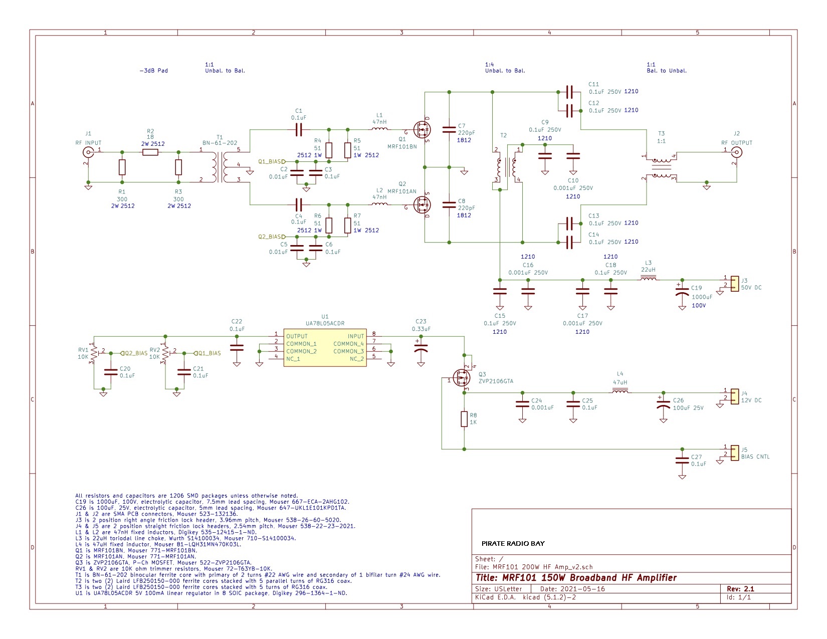
ΚΑΤΑΣΚΕΥΗ ΠΟΜΠΟΥ HF ME TO mrf101-200whf-amp_v2-1
ΠΑΡΑΚΑΤΩ ΤΟ ΣΧΗΜΑΤΙΚΟ ΜΕ ΤΑ ΥΛΙΚΑ ΤΗΣ ΚΑΤΑΣΚΕΥΗΣ
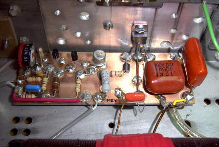
ΚΑΤΑΣΚΕΥΗ AUTOMATIC TEMPERATURE CONTROLED FAN
ΥΛΙΚΑ ΚΑΙ ΣΧΕΔΙΟ ΠΑΡΑΚΑΤΩ


I've had many requests for a ready-made J-pole design that will enable the
Packet Radio user to print the image from a web page and go directly to the
construction table and build a J-Pole antenna for their Packet Radio station.

The object is to eliminate the need to go through all the calculations on
another page of this website.  These requests are valid and understood!
With your requests in mind, here are "the real world" designs that I've
personally constructed and use at many of my Packet Radio node locations.
 A VARIATION ON A THEME:

Let's look first at FIGURE 1a;  This is the overview and profile of the
J-Pole we will be working with.  There are two different bands we will be
building the J-Pole antennas for.  NO, we will not build a two band antenna
on one mast.  I've been there, done that.. and it is an excercise in futility.

For openers, I would like to show you that all J-poles are not created equal.
By that statement I mean, we will modify our construction techniques a bit
and apply a variation to the theme.

Notice in the exploded view at FIGURE 1b, I've deviated from the usual RF feed
technique that we normally use to attach our coaxial cable to the J-pole.

Where we usually attach the shield and center conductor to the tuning stub and
the driven element with aeroseal (hose) clamps, here we've made a slight change
in the design by exchanging the elbow for a tee.  Below the short (1/4 wave
tuning stub) section, we (carefully) soldered an SO-239 (Chassi-mount) coax


| |||||
|
Frequency
Inductance Capacitance Calculators for FM
Oscillators
|
  |