''ΕΡΑΣΙΤΕΧΝΙΚΟ ΔΥΚΤΙΟ ΕΛΛΑΔΑΣ ΝΟΣΤΑΛΓΙΑ''
H ΚΑΛΥΤΕΡΗ ΕΛΛΗΝΙΚΗ ΜΟΥΣΙΚΗ ΑΠΟ ΤΑ 1960 ΜΕΧΡΙ ΣΗΜΕΡΑ ΟΛΟ ΤΟ 24ΩΡΟ . Ο ΣΤΑΘΜΟΣ ΤΩΝ ΜΕΓΑΛΩΝ ΕΠΙΤΥΧΙΩΝ ΤΟΥ ΕΛΛΗΝΙΚΟΥ ΠΕΝΤΑΓΡΑΜΟΥ ΣΤΗΝ ΕΛΛΑΔΑ ΜΕ ΕΚΠΛΗΚΤΙΚΗ ΠΟΙΟΤΗΤΑ ΗΧΟΥ HD.
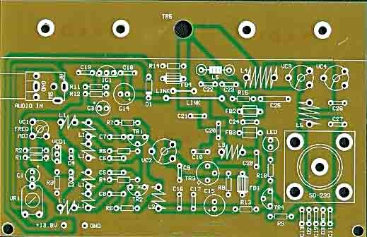
ΕΝΙΣΧΥΤΗΣ RF 1 W FM Amplifier 2SC1970- 2Ν4427 88-108 MHz SOS ΑΠΟ ΕΞΟΔΟ PLL 50 mWATT
1.3W VHF RF Amplifier 2SC1970 88-108 MHz
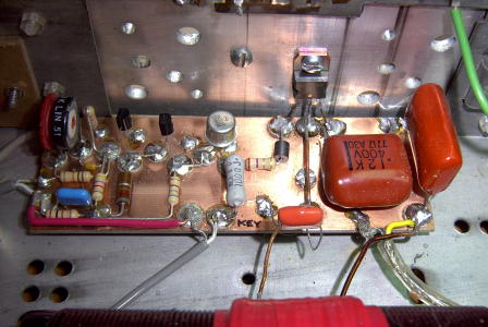
This RF power amplifier is based on the transistor 2SC1970 and
2N4427. The output power is about 1.3W and the input driving power is
30-50mW. It will still get your RF signal quit far and I advice you to
use a good 50 ohm resistor as dummy load. To tune this amplifier you can
either use a power meter/wattmeter, SWR unit or you can do using a RF
field meter.
ΕΤΣΙ ΑΠΛΑ ΚΑΝΟΥΜΕ ΑΠΟΧΑΛΚΩΣΗ!! ΑΚΟΛΟΥΘΗΣΤΕ ΤΗΝ ΕΥΚΟΛΗ ΚΑΙ ΑΞΙΟΠΙΣΤΗ ΛΥΣΗ !!
ΑΠΟΧΑΛΚΩΣΗ ΤΥΠΩΜΕΝΟΥ
Η αποχάλκωση γίνεται με διάφορα υγρά αποχάλκωσης και διάφορους τρόπους. Εγώ χρησιμοποιώ τα ακόλουθα υγρά και τον εξής τρόπο: Σε μια μικρή πλαστική λεκάνη βάζω κάποια χημικά υγρά σε διάφορες αναλογίες. Πρώτα βάζω 50 gr υδροχλωρικό οξύ(HCL) ΑΚΟΥΑ ΦΟΡΤΕ που το αγοράζω από το σούπερ μάρκετ. ....
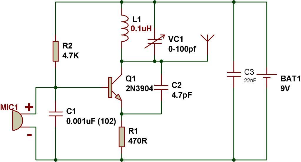
This tutorial is for making simplest FM transmitter using only one transistor. VC1 is a small, screw-adjustable, trimmer capacitor and its rating should be around 10-100pF. Set your FM receiver for a clear, blank station.
Then, with a non-conductive tool, adjust the capacitor for the clearest reception, rotate it till the receiver receives a sound from the microphone of transmitter. Use the following formula for determining the frequency.
The schematic of FM transmitter:
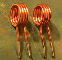
The following shows the components used to make FM transmitter:
100W Transmitter Amplifier for 2MHZ ΑΚΟΛΟΥΘΗΣΤΕ ΠΙΣΤΑ ΤΟ ΣΧΕΔΙΟ
100W Transmitter Amplifier for 2200m
100W Transmitter Amplifier for 2200m
This particular transmitter was later shipped up to VY1JA in the Yukon where, thanks to Jay's excellent antenna system, it was heard in Europe as well as in New Zealand during one of the Trans-Pacific Tests! Running 24 volts on the final will produce 100 watts into a 50 ohm load. The transmitter utilizes a 4060 binary counter IC chip as both the crystal oscillator and frequency divider. I used a 2200 kHz crystal along with the 'divide-by' sixteen output to produce a signal at 137.5 kHz. Other combinations of crystal frequencies and 'divide-by' combinations may also be used since the 4060 features divided outputs for f/32 (pin 5) and f/64 (pin 4), among others. You may have a 4MHz crystal or an 8MHz crystal in your junk box that will put you in the band using these output pins.
This transmitter is based, more or less, on equations presented in a 1988 Mark Mallory article detailing a single-ended class-E output stage for a 1-watt transmitter operating in the 160-190 kHz Part-15 LowFER band. The present circuit is a push-pull design and achieves about 93% efficiency at 1710 kHz. The circuit should be adaptable to transmitting in the 160-meter ham band with slight component value changes, or to any frequency within the medium or longwave bands (0-2 MHz) by following the design steps below. The 'as-built' transmitter can be tuned about 100 kHz either side of 1710 kHz (1600-1800 kHz) without modification.
The transmitter has the same basic layout as any AM transmitter, though it may differ in specifics. A block diagram of the as-built unit appears below. Refer back to this diagram as the parts are explained in the article below. Items marked "external" are not described (except in a general way) in the article.
In this article LodeRunner explains
what an Inverted-L antenna is, how it works, and why you might strongly
consider building one for use on the lower bands. While explaining its
use with a high degree of technical information, he’s written it in a
manner that’s easy to follow and digest. The diagram data is sourced
from EZ-NEC, which a link to the software is provided in the sidebar.
The Inverted-L Antenna and NVIS
An
“Inverted-L” antenna is basically a wire antenna, typically ¼ to ½
wavelength long on the band it is designed for. The Inverted-L antenna
is a common antenna for the 160 meter and 80 meter amateur bands, where
typical ¼ wave verticals are impractically tall for most amateurs.
In
the Inverted-L configuration, the first portion of the wire rises
vertically from the feedpoint, and at some height is bent roughly 90
degrees, and then extends horizontally to the unterminated end. The
feedpoint is very close to ground level (typically not more than 3 feet
above ground), and the antenna is worked against a Ground consisting of
one or more ground-rods, and/or a counterpoise consisting of one or more
radial wires – which may be buried, laid directly on the ground, or
suspended above the ground at some low height.
Because
the input impedance of a typical Inverted-L antenna is low, and the
feedpoint is at or very close to ground level, where ground losses are
substantial, it is very important to establish a good ground to work the
antenna against.
Most
of the amateur literature regarding the Inverted-L antenna is focused
on optimizing performance of the Inverted-L antenna for “DX” operation –
that is, high efficiency in radiating its energy in a pattern that is
low in elevation (low Take-off Angle, or ToA) – typically below 30
degrees relative to the horizon – which maximizes the distance to which
communications may be achieved. Effective NVIS communications, on the
other hand, require an antenna which is optimized to produce a pattern
where the majority of the radiated energy has a high ToA pattern –
ideally between 60 and 90 degrees – to provide reliable communications
from zero to several hundred miles.
Fig. 1: DX dipole pattern on 80 Meters
First, lets take a look at the difference between a good “DX Antenna” pattern vs. a good “NVIS Antenna” pattern –
Figure
1 is a diagram of a dipole optimized for DX communications; Figure 2
represents the exact same dipole, but the height has been lowered by
approximately 1/3 wavelength to optimize the antenna pattern for NVIS
communications.